You have invested hundreds of thousands in a flotation machine, yet recovery rates remain stubbornly low—where exactly does the problem lie? When purchasing флотационные машины, many mining enterprises focus heavily on brand and price while overlooking the compatibility of core components. Common issues include fluctuating aeration rates, unstable froth layers, impellers wearing through within just six months, and improper froth scraper adjustments that cause significant concentrate loss into the tailings. Ultimately, the root causes of these problems often trace back to 7 key components: the corrosion resistance of the tank material, the precision of the clearance between the impeller and stator, and the alignment of the froth scraper speed with slurry characteristics. From the perspectives of both purchasers and operators, this article provides an in-depth analysis of the 6 flotation machine components: impeller, stator, tank, froth scraper, aeration system, discharge mechanism, and drive system, helping you maximize equipment performance and minimize O&M costs in your mineral processing operations.
What Is Flotation Machine?
(1) Definition
Flotation machines (or flotation cells) are primarily designed to efficiently separate valuable minerals from gangue through the selective attachment of air bubbles to mineral particles. Based on their structure, they are categorized into three main types: mechanically agitated, pneumatically agitated, and flotation columns. Among these, the mechanically agitated type—which generates negative pressure to draw in air via impeller rotation—is the most widely used and holds a dominant market position. These machines are extensively employed in the beneficiation of metals such as copper, lead-zinc, molybdenum, nickel, gold, and lithium, as well as in the purification of non-metallic minerals like phosphate rock, fluorite, graphite, and barite. Furthermore, флотационные машины are particularly well-suited for processing copper, lead, zinc, золото, and lithium, serving as core equipment in mineral processing workflows.
(2) Principle
After the pulp (slurry) is mixed with reagents, it enters the flotation cell, where the high-speed rotation of the impeller creates negative pressure that draws in air. The impeller shears the air into fine bubbles while simultaneously agitating the pulp to ensure thorough contact between the minerals and the bubbles. Added collectors alter the surface properties of the target minerals from hydrophilic to hydrophobic, enabling them to attach to the bubbles. Hydrophobic mineral particles adhere to the bubble surfaces, forming mineralized bubbles that rise to the liquid surface. These mineralized bubbles accumulate at the surface to form a froth layer, which is then removed by a scraper to yield the concentrate; meanwhile, hydrophilic gangue particles sink and are discharged from the bottom of the cell. This entire process takes place continuously across multiple flotation cells, requiring precise control over reagent dosage, bubble size, and pulp concentration to achieve the efficient separation of minerals from waste rock.
7 Key Flotation Machine Components & Their Functions
Component 1: Tank / Cell Body
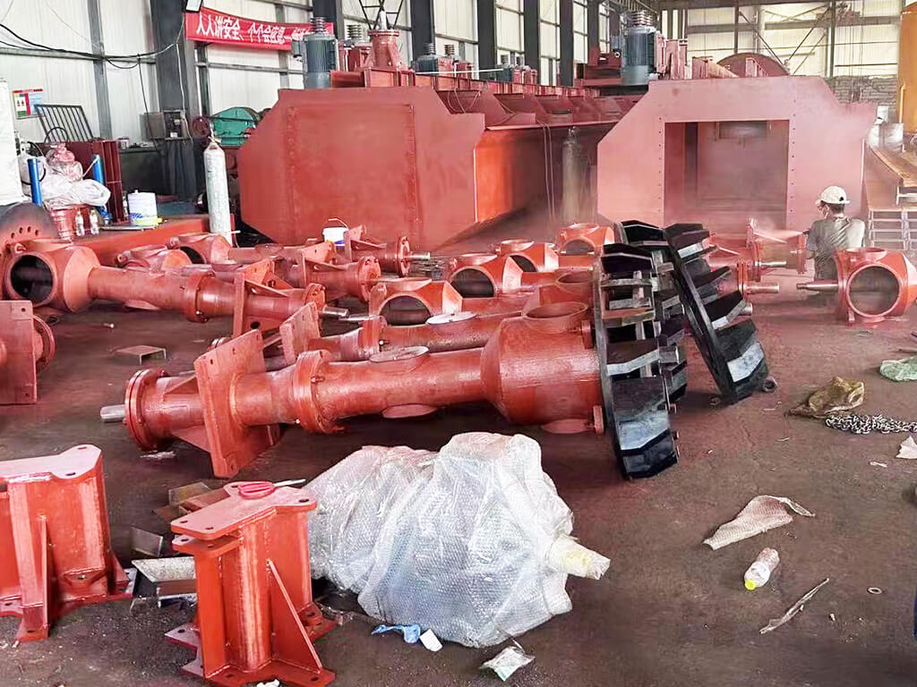
The tank serves as the structural foundation of the flotation machine, housing the complete processes of slurry agitation, aeration, and separation. Among all flotation machine components, the tank is the largest and most costly structural element. Typically constructed from rubber-lined carbon steel to balance corrosion and wear resistance, the tank directly influences the equipment’s service life. Cylindrical tanks offer superior hydrodynamic performance, whereas rectangular designs are better suited for large-scale, series-connected configurations. Furthermore, the internal false bottom works in tandem with the draft tube to stabilize slurry flow and minimize the formation of eddies.
Component 2: Impeller (Rotor)
The impeller is primarily responsible for agitating the slurry, self-aspirating air, and shearing the air into fine bubbles. Impellers made of high-manganese steel are the preferred choice for processing high-hardness ores due to their exceptional wear resistance. Star-shaped impellers feature a simple structure and high air intake capacity, making them suitable for roughing operations. Impellers with radially chamfered blades provide stronger shearing forces and produce more uniform bubbles. Additionally, while larger impeller diameters and higher rotational speeds increase aeration volume, excessive values can lead to oversized bubbles and increased energy consumption.
Component 3: Stator
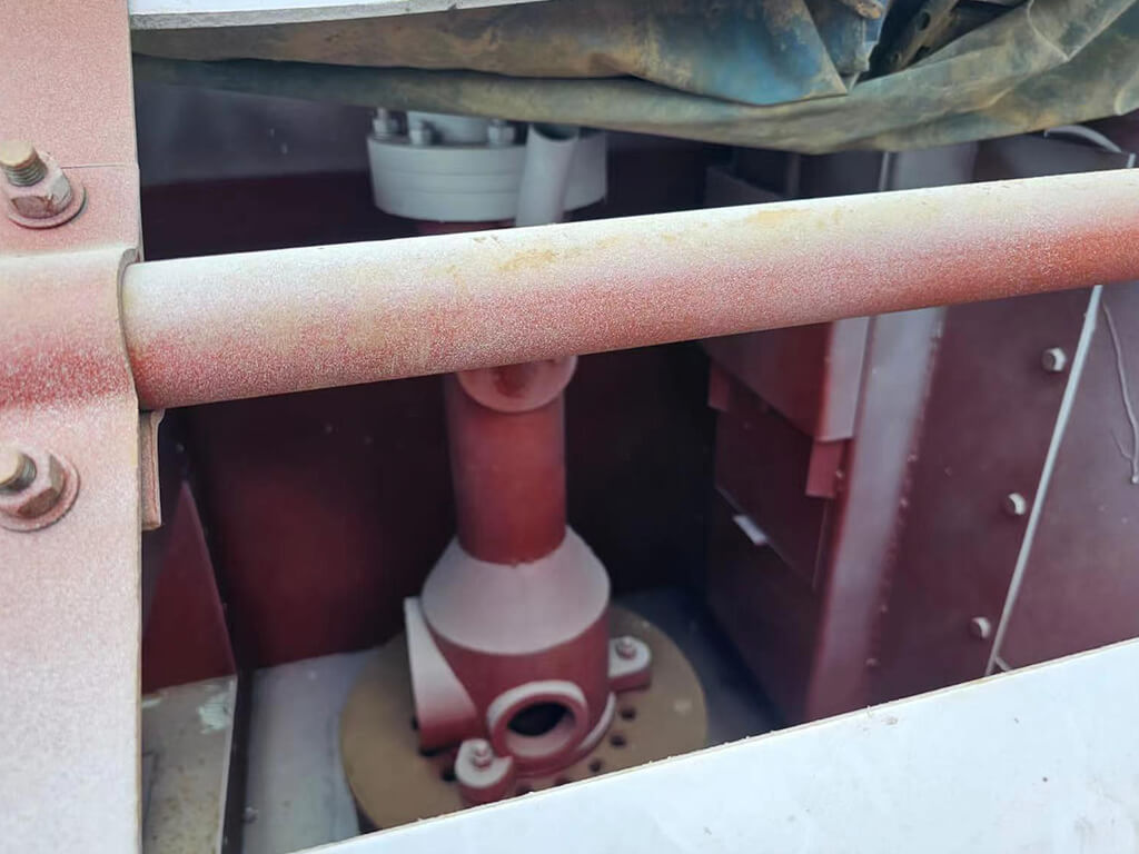
The stator is installed around the impeller and serves three primary functions: directing flow, stabilizing flow, and assisting in the formation of a negative-pressure zone. The stator blades are positioned at a 60-degree angle relative to the radius, allowing them to smoothly guide the slurry discharged by the impeller to various parts of the tank. Among all flotation machine components, the precision of the fit between the stator and the impeller directly impacts separation efficiency. Therefore, the clearance between the stator and the impeller should ideally be maintained within the industry-standard range of 2–5 mm; this minimizes unnecessary energy loss while ensuring ample opportunity for contact between air bubbles and mineral particles.
Component 4: Froth Scraper Mechanism
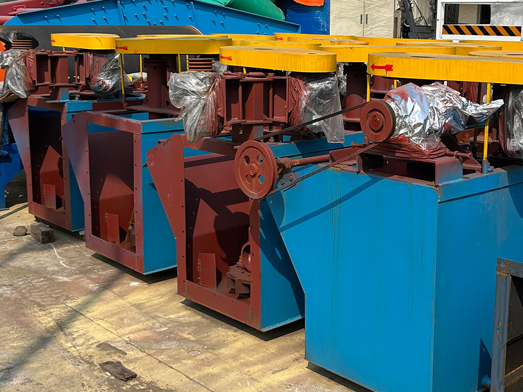
The froth scraper mechanism is responsible for skimming mineralized froth from the liquid surface into the concentrate launder, serving as a critical component of the flotation discharge process. A single-sided scraper design is simple and suitable for small-scale equipment, whereas a double-sided configuration offers higher efficiency and is better suited for large-scale flotation machines. The scraper speed must match the froth layer thickness; excessive speed can drag pulp into the concentrate, thereby lowering the grade, while insufficient speed results in delayed froth overflow. A froth-pushing cone device can accelerate froth flow toward the discharge lip, reduce residence time, and enhance concentrate recovery efficiency.
Component 5: Aeration System (Air Intake & Dispersion)
Self-aspirating aeration systems utilize the negative pressure generated by impeller rotation to draw air directly into the tank; featuring a compact design and requiring no external air source, they are suitable for small- to medium-sized processing plants. In contrast, forced-air systems rely on an external blower for an independent air supply, allowing for flexible adjustment of airflow based on process requirements—an advantage particularly evident in large-volume flotation machines. Air travels through the intake pipe and air-guiding sleeve into the impeller zone, where it is sheared at high speed into fine bubbles.
Component 6: Discharge Mechanism & Froth Launder
The discharge and launder system is primarily responsible for collecting and discharging concentrates and tailings, directly influencing the operational continuity of the process. The concentrate launder employs either a peripheral overflow or a radial launder design; peripheral overflow is suitable for large tank bodies, whereas radial launders offer faster froth discharge rates. Tailings are discharged through a bottom outlet pipe, with a gate adjustment mechanism controlling the slurry level to maintain a stable froth layer. An automatic level control system—utilizing either float-type or pressure-sensor-type sensors—enables real-time adjustment of the discharge rate.
Component 7: Drive System (Motor, Shaft, and Bearings)
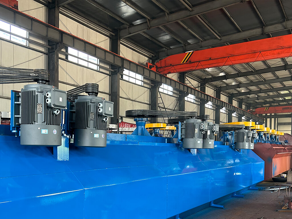
The agitation motor drives the rotation of the impeller; as its power requirement is significantly higher than that of the scraper motor, factors such as tank volume and slurry density must be carefully considered during selection. The main shaft and bearing housing utilize labyrinth or air seals to effectively prevent slurry from penetrating the bearings and causing damage. V-belt drives are simple in structure and easy to maintain, and are widely used in small and medium-sized equipment. Although variable frequency speed control entails a higher initial investment, it offers significant energy savings during operation and allows for more precise and flexible parameter control.
Common Flotation Machine Issues & Component Fixes
| Common Issue | Possible Cause | Components Involved | Решение |
|---|---|---|---|
| Recovery rate drops | Impeller wear leads to insufficient aeration | Рабочее колесо | Replace promptly when wear exceeds limits |
| Froth layer too thin | Low aeration volume or excessive stator clearance | Stator, Aeration System | Adjust clearance and clean the intake pipe |
| Low concentrate grade | Scraper speed too high, drawing in pulp | Froth Scraper Mechanism | Reduce speed and increase froth layer thickness |
| Corrosion or wear on inner wall | Improper material selection or abnormal pulp pH | Резервуар | Replace lining material (e.g., rubber or polyurethane) and adjust pH |
| Bearing noise or overheating | Bearing wear or loose belt | Drive System | Apply specialized grease or adjust belt tension |
| Large fluctuations in aeration volume | Aeration device clogged or insufficient pressure | Aeration System | Clean air vents and check blower condition |
| Severe coarse particle loss in tailings | Liquid level too high or improper gate adjustment | Discharge System | Lower liquid level and check gate opening |
| Uneven froth scraping | Scraper deformation or incorrect speed setting | Froth Scraper Mechanism | Correct scraper curvature and optimize parameters |
Заключение
The 7 key flotation machine components including tank/cell body, impeller, stator, froth scraping mechanism, aeration system, and drive system, each perform indispensable functions. From the tank material selection and impeller wear resistance to the precision of stator clearances and the rotational speed matching of the froth-scraping mechanism, the synergy among these components directly determines the machine’s separation efficiency and service life. Only through a deep understanding of these components can long-term, stable equipment operation be achieved, effectively reducing the processing plant’s overall operating costs. Ultimately, the true performance of a flotation machine is not defined by its outer casing, but by the precision coordination of these 7 key components.
Requirements regarding component materials and configurations vary depending on ore characteristics and production capacity needs. Should you have any questions regarding flotation machine selection or component replacement, JXSC горный машиностроительный завод offers customized mineral processing solutions tailored to your specific operating conditions.
 English
  Spanish
  French
  Russian